Article courtesy Underhood Service.
Fuel pumps and voltage drops are almost never a good combination — at least the wrong kind of voltage drops.
Good voltage drops occur with fuel pumps that are given multiple speeds with a module that is connected to a computer with a dedicated signal wire that tells the module to go to a lower or higher speed. Good voltage drops also come from a serial data bus, like on vehicles with a Controller Area Network (CAN) bus-controlled fuel pump module. Either way, we can control fuel pump speed by reducing the voltage, or by turning the fuel pump off and on with a pulse width-modulated output.
These types of voltage drops are fine because we want the fuel pump to run at different speeds based upon the engine’s demand for fuel. But, if it’s a system that’s supposed to have full charging voltage, such as a 12.5-volt or 14.5-volt system, and the engine’s running the fuel pump in order to make the right amount of fuel to go into the engine with a particular pulse width on the injectors, then it needs to have the correct voltage supplied to it.
While running a fuel pressure test can tell you if the pump is providing the correct amount of fuel pressure or not, it cannot tell you why it’s not producing the correct fuel pressure or volume under a wide range of conditions. Using just a fuel pressure gauge to diagnose a fuel-related problem could lead to an incomplete repair and a comeback, especially if it’s intermittent or causes problems under load.
Some of the best diagnostic tests for fuel pumps are voltage drops and current testing. Fuel pressure and volume are influenced by voltage, current and the demand controlled by the regulator. If a fuel pump is not receiving the correct voltage, it cannot spin fast enough. Voltage drop testing can isolate problems that can still remain even if the pump is replaced.
Voltage drop testing compares the battery or charging voltage to the voltage at the component. The voltage drop occurs because of resistance in the circuit that supplies the pump. The resistance could be in the connectors, grounds or harness.
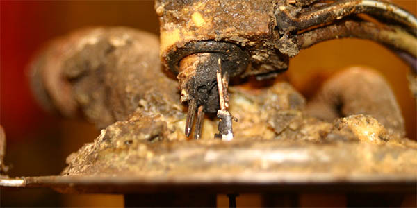
A resistor or insulator prevents the flow of electricity in a circuit. Resistance can be caused by corrosion, fretting and even air. If you were to put a 1.0-ohm resistor in a fuel pump circuit, it would lower the 13.25 volts prior to 9.78 volts. This is a voltage drop of almost 4.0 volts. The loss of 4.0 volts may not affect the idle of a vehicle, as the fuel pressure may be within specifications. But, when more volume is required, as when the vehicle is under acceleration, it could be starved for fuel.
It doesn’t take much to introduce 0.5 ohms or more of resistance into an automotive electrical circuit. It could be caused by a corroded ground, a connector that is no longer sealed or even a connection that is weak due to poor retention.
TESTING VOLTAGE DROPS
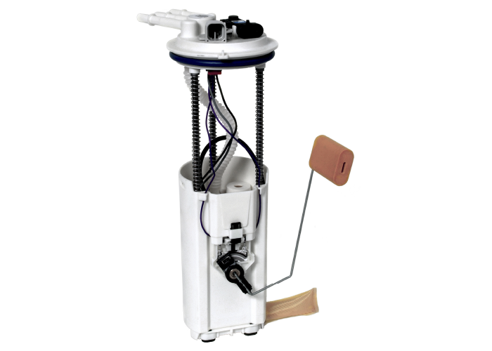
A voltage drop test is the only effective way to find excessive resistance in high-amperage fuel pump circuits. With the right leads and back-probes, it’s possible to do the test (if you have access to the top of the tank) without any disassembly. The results are immediate as to whether you’ve got a good connection or a bad one.
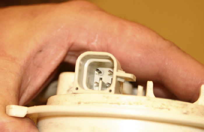
Since the fuel pump circuit must be energized, you will need to back-probe the connectors or pierce the wires. Some connectors can be disassembled to access the terminals. More than likely, you’ll have to pierce the wire to take a reading. It’s highly recommended to use specialized piercing probes. Using thumbtacks and pushpins can damage the connector or wires. If you damage a wire, it’s highly recommended to seal the puncture with electrical tape. Most fuel pump wiring harnesses reside in a harsh environment.
VOLTAGE DROP TEST PROCEDURES
1. Address the negative side of the circuit first, then the positive side.
2. Connect one digital voltmeter test lead to the negative battery terminal and the other to the negative terminal at the fuel pump.
3. The fuel pump circuit must be energized to properly test it. Energize the fuel pump relay and power the fuel pump circuit. The majority of fuel pumps run for only a few seconds once the relay is energized (only long enough to prime the system) and until an RPM signal is generated.
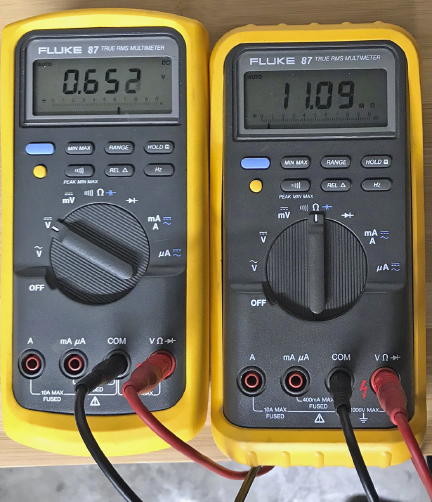
4. If the negative circuit is in good condition, the voltage drop measured should be 0.5V DC or less. Larger voltage drop readings indicate a problem. Damaged or corroded vehicle wiring or harness connectors are likely sources of the problem.
5. Repeat the voltage drop test on the positive side of the circuit. Connect one digital voltmeter probe to the positive terminal on the battery and the other to the positive fuel pump terminal.
6. Energize the fuel pump relay and power the fuel pump circuit. The majority of fuel pumps run for only a few seconds once the relay is energized (only long enough to prime the system) and until an RPM signal is generated.
7. As with the ground circuit, voltage drop readings larger than 0.5V DC indicate system wiring or connector issues.