MODELS:
2015-2019
- Cadillac Escalade
- Chevrolet Silverado 1500, 2500 and 3500
- GMC Sierra 1500, 2500 and 3500 GMC Yukon
CONDITION:
Some owners may comment on any of the following issues
- Service ABS and/or Traction control lights/message on.
- Service Power Steering System, if equipped with electric power steering.
- Service Suspension System, if equipped with RPO Z95.
- Backup reverse camera inoperative.
- Backup camera grid or guidance lines missing/inoperative.
- Vehicle Settings icon grayed out.
- Loss of communication with EBCM, SDGM, SDM, SWPS, PSCM, PTO, HMI, and/or SCM (if equipped).
DTCs:
- B127B
- U0077
- U0117
- U0121
- U0126
- U0131
- U0139
- U0151
- U0401
- U0415
- U0428
- U18A3
- U2179
These concerns could be caused by high resistance, open or short in the Communication Enable Circuit 5986. The BCM activates this circuit when the ignition key is in ACC, ON and START positions (There will be voltage present in the OFF position only for a short time until the BCM goes to sleep). The communication enable circuit wakes up the module for serial data bus communication. Circuit 5986 will have approximately 12 volts and should light a test light, but is not designed to handle heavier electrical loads like a headlight bulb.
Service Procedure:
Monitor the voltage on the communication enable circuit 5986 at any of the modules affected, example EBCM, SDGM, PSCM, SWPS, SDM, HMI, PTO, and/or SCM. If low voltage or no voltage is present when the concern occurs, inspect for open/high resistance/shorts on circuit 5986. Repair any opens, high resistance or shorts in the circuit.
Tips: Circuit 5986 is a low-amperage signal circuit and it may not be able to power certain test lights or bulbs. The use of a voltmeter and small bulb, example 194 bulb, is required to load test the circuit. With a battery charger/maintainer connected to the vehicle, attach one side of a 194 bulb to circuit 5986 (at the suspect module) and the other side to a good ground. Next, wake up the BCM (by turning the headlights on or turning the ignition on) and make sure the bulb lights.
If the bulb does NOT light, inspect for high resistance, open and shorts in circuit 5986. If the bulb lights, use a voltmeter and measure the voltage across the 194 bulb, to make sure there is at least 11 volts. If not, inspect for high resistance, open and shorts in circuit 5986. A 194 bulb draws approximately 250 mA. Attaching too much of a load to circuit 5986 will pull the voltage down below 11 volts and lead to misdiagnosis.
The BCM monitors circuit 5986 for an excessive amperage draw and will shut down the output on circuit 5986 if it draws more than 0.88 amps (example short to ground). The BCM 1 and BCM 2 fuses are what the BCM uses to feed power to circuit 5986.
Here are three known areas where circuit 5986 has been found to be open/shorted or have high resistance:
- On short wheelbase utilities (Escalade, Tahoe and Yukon), the chassis harness may be cut, pinched or shorted between the body and spare tire crossmember. See latest version of PIT5556 for more details.
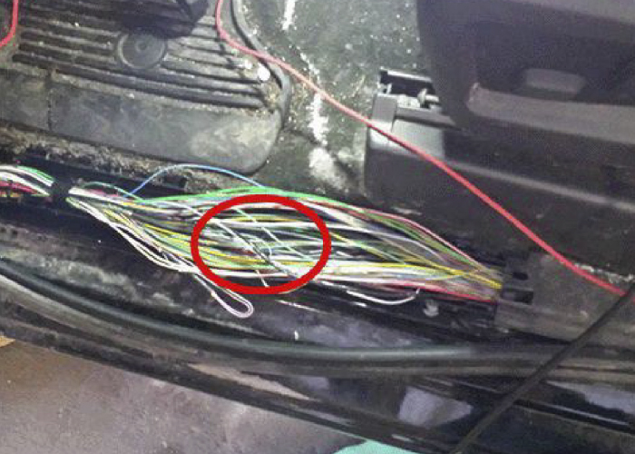
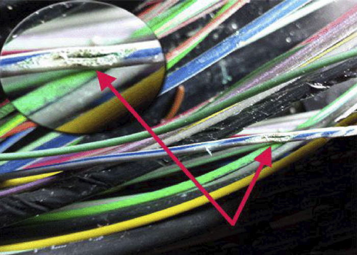
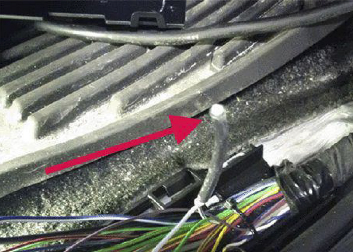
- Under the driver’s sill plate, shown in Figures 1 and 2.
- Splice J365 located under the passenger front sill plate, shown above in Figure 3
This article is courtesy of Brake & Front End.