Many automakers, including Toyota, Nissan and Honda, have reengineered their drivetrains to be more efficient. These engines have longer strokes and less displacement to improve fuel economy by making more power at lower engine speeds. But because these new engines increase the stroke, but not the bore, it can make for some unique vibration conditions the motor mounts have to minimize.
Even in the modern V6, many manufacturers have ditched the balance shafts to reduce drag on the engine. And, V6 engines from Honda are using cylinder deactivation that can turn a smooth V6 into a three-cylinder engine. These changes have made the engine mount’s job even harder.
Why Active?
Solid motor mounts are a compromise between the comfort and control of the movement of the engine. Hydraulic or fluid-filled mounts offered a more flexible range of vibration dampening. The next step in the evolution is active motor mounts.
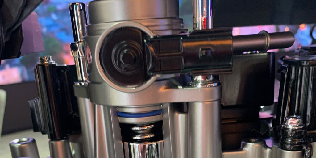
Many companies that make active motor mounts also make active shocks. The similarity between the active motor mounts and active shocks is the valving and the combination of rubber with steel. The valving inside a motor mount controls the flow of fluid between chambers in the motor mount. The smaller the opening in the valving, the stiffer the mount gets. When the valving fully opens, the fluid flows smoothly between chambers and the mount becomes less rigid. Most active systems use engine vacuum or an electrical solenoid to control the movement of a diaphragm that controls the internal pressure inside the solenoid.
Toyota mounts use a vacuum to control the mount’s characteristics. Engine speed is the primary input that determines the stiffness of the mount. The amount of engine vacuum supplied is controlled by a solenoid connected to the engine vacuum. The duty cycle vacuum switching valve (VSV) is controlled by the powertrain control module.
When the engine is idling, the PCM completes the ground circuit to the VSV solenoid, allowing the intake vacuum to be applied to the mount. This makes the mount more compliant, and it can absorb more vibration and shake. At higher engine speeds, the PCM reduces the frequency of the pulse signal to the VSV to gradually increase the stiffness of the mount to match engine speed.
Toyota VSV solenoids and mounts are tested with a meter and vacuum pump. Using a vacuum pump, apply -11.5 psi. The mount should be able to hold the vacuum for more than one minute. It is critical to inspect the vacuum line from the solenoid to the intake manifold. A leak will not only cause the mount to be inactive, but the vacuum leak could cause lean codes and random misfire codes. A leak and damaged mount can make for a very rough running engine.
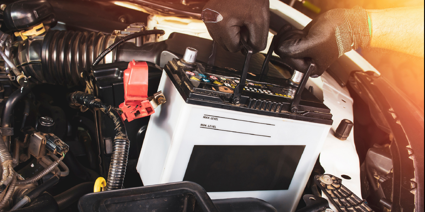
The solenoid can be tested with battery voltage to confirm the operation. A meter can also be used to verify the resistance value of the solenoid. The power that controls the solenoid is a pulse-width-modulated signal that goes between 0 and 12 volts.
The Honda Active Control Mount (ACM) system uses an electromechanical plunger that puts pressure on a diaphragm in the motor mount. The plunger quickly controls the stiffness of the mount.
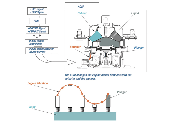
The ACM mounts are controlled by a dedicated module under the hood. The module uses the camshaft and crankshaft position sensors’ inputs to predict engine vibrations. This strategy is used when the engine goes into cylinder deactivate mode when only three cylinders are active. The system is also active to minimize shudder when the transmission is shifting, or the torque converter clutch is locking up.
In the past, you could get away with a just a visual inspection and maybe putting the engine into gear. Active motor mounts add a new wrinkle to the inspection and diagnostic process of evaluating a motor mount. So, if you see a connector on the side of a motor mount, you might want to check for codes.