The evaporative (EVAP) emission system has an important job to do: to reduce or eliminate the possibility of hydrocarbons being released from the fuel system into the atmosphere. A number of components all work together to prevent fuel vapor from escaping, route it to the intake manifold to be burned during normal combustion, and perform self-checks to identify any possible leaks in the system.
EVAP diagnostics can be a frustrating task for techs. Working on luxury imports such as Audi can further complicate things. Let’s look at some of the things that you should know about Audi EVAP systems before trying to tackle such a repair.
System Self-Check & Overview
During the self-check procedure, the pressure reading inside the system is monitored by the Engine Control Module (ECM) for a specific period of time. If the pressure drops more than a specified amount during that time, the system will repressurize the system again. By measuring how much pressure is lost and how much time it takes for it to drop, the ECM is able to determine the size of the leak.
This self-check usually activates shortly after the engine is started. If the system detects a leak, a Diagnostic Trouble Code (DTC) will be stored in the ECM memory. If it occurs on the next drive cycle, the Malfunction Indicator Lamp (MIL) will illuminate.
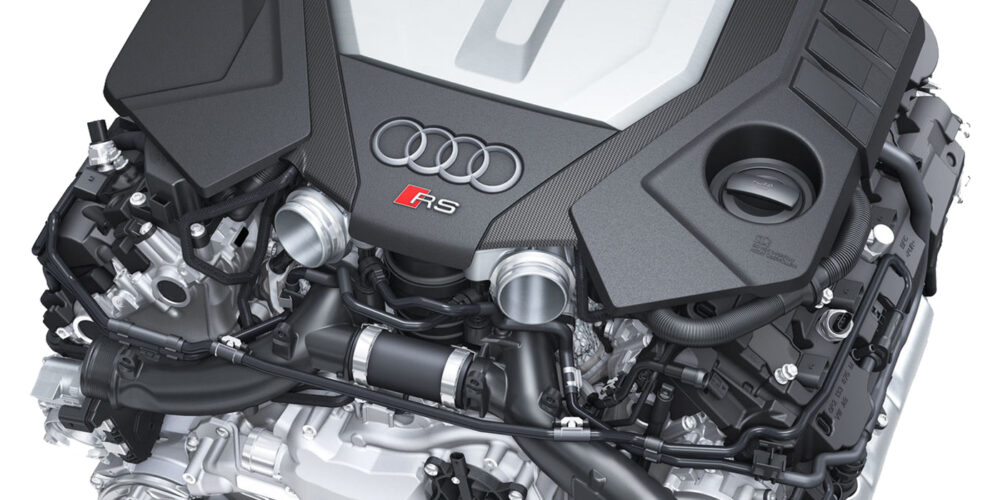
Let’s look at the EVAP system on a 2014 Audi S6 4.0T as an example of how complex Audi’s EVAP systems can be (Figure 1). These engines are packed tightly into the engine bay, and there’s a lot going on. As you can see, the EVAP line set is a singular unit, bridging the connections between the charcoal canister, the intake manifolds, and the relevant sensors. The ECM controls when the fuel vapors stored within the charcoal canister are allowed to enter the engine. This is achieved by activating the EVAP canister purge regulator valves for each bank (N80 & N115 in Figure 1).
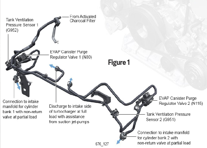
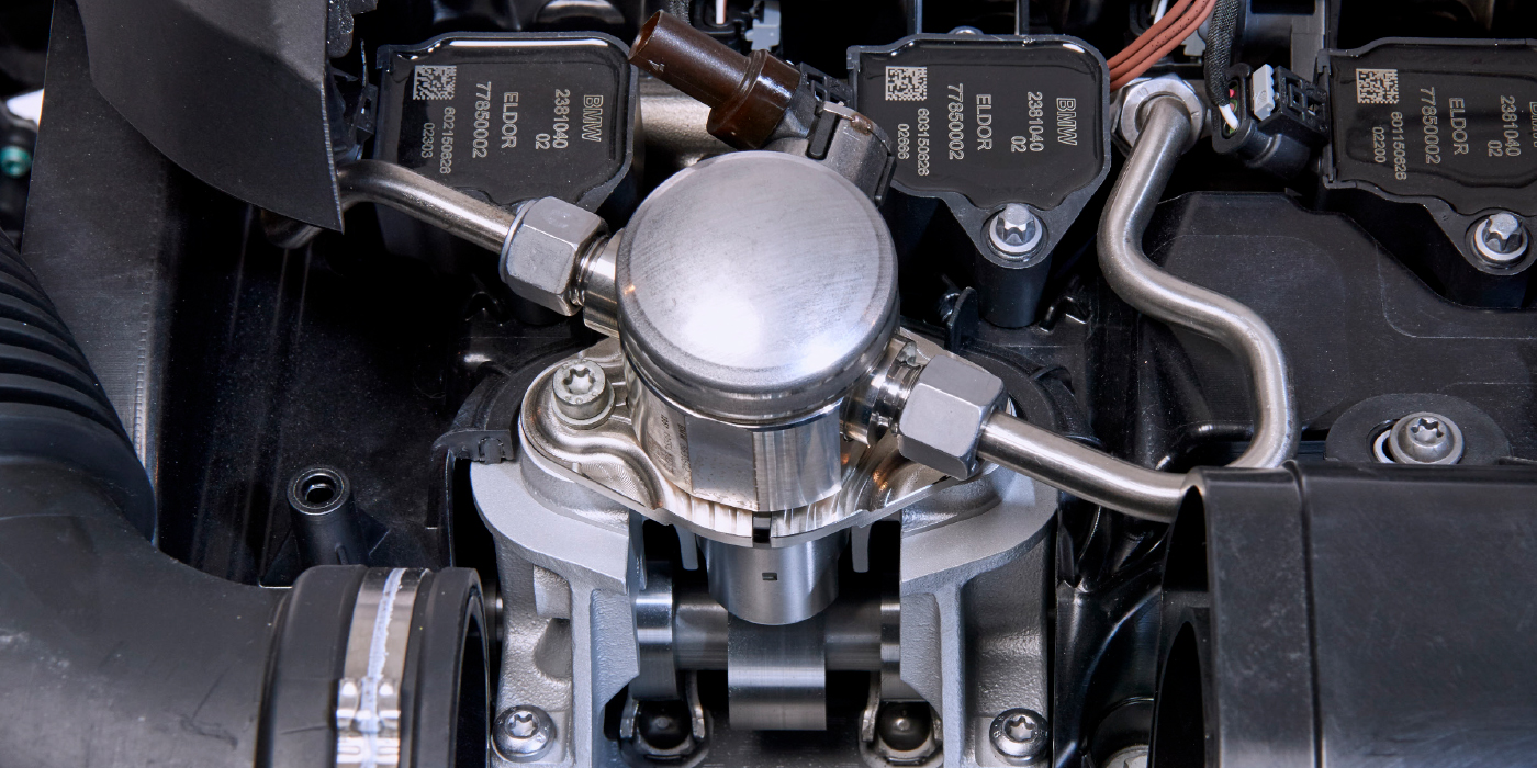
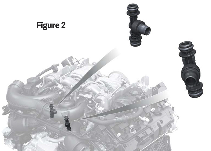
When engine vacuum is present, the charcoal canister is allowed to vent via the non-return valves in the intake manifolds. When boost pressure is present, venting will take place in front of the turbocharger instead of via the two suction jets which are located underneath the charge pipe (Figure 2). These suction jets operate on the Venturi principle. When vacuum drops, for example, at full load, the pressure difference causes a “Venturi effect,” and the fuel vapors are able to vent from the canister and into the intake side of the turbochargers.
Common Failure Points
Now let’s talk about where things can go wrong. As with all things, EVAP components can, and will, wear out over time. Years of heat-cycling inside the engine bay can take a toll on the plastic pipes, fittings, and connectors. They will eventually become brittle, fragile even, and if mishandled or stressed, they can break easily. The rubber hoses are vulnerable in the same way, but they may exhibit signs of dry rotting, as well.
In my own experience, most of the EVAP failures I saw were caused by some sort of abuse, neglect, or some other outside force. For example, a worn out set of engine mounts can cause the engine to move excessively during normal operation. This movement could cause hoses, pipes, or lines to stretch, or even rub up against other nearby components. If left alone, they could rub all the way through and cause an EVAP leak.
Any time you’re working on an EVAP system, it’s wise to inspect all of the mounting points and/or brackets which support the EVAP pipes and hoses, and check for any signs of interference with neighboring components. When performing a leak test, don’t forget to check all of the connection points, as well as anywhere the plastic pipe transitions to rubber hose and back again.
Pressure sensors and purge valves will also wear out over time, but don’t be too quick to condemn them. A bent pin inside the connector could cause erroneous readings. The harness could be damaged due to rubbing against the engine, or rodent damage. The bottom line is that you want to follow the diagnostic process all the way through. As a wise man once told me: “test, don’t guess.”
Tips & Tricks
As always, it is best to always check the OEM service information for all relevant system component locations, hose routing, removal/installation procedures and torque specifications, wiring diagrams, etc.
After an EVAP repair has been completed, you’ll need to erase the DTCs from the ECM memory. This will also delete the readiness code, also known as the EVAP readiness monitor. The readiness monitor is the self-check we discussed earlier. So, once the ECM performs that self-check and no leaks are detected, the readiness monitor will pass and the vehicle has been repaired.
You can manually run the monitor as part of your post-repair road test. There are a few prerequisites which must first be met:
- Erase the DTC memory.
- Fuel tank level at 1/4 to 3/4 full.
- Battery voltage must be a minimum of 12.5 volts.
- Coolant temp must be 176-230 degrees F.
- Intake air temp must be 50-95 degrees F.
Now, here’s how to execute the EVAP monitor. Please note that smooth acceleration during the drive cycle may help the monitor to complete faster and easier:
- Connect the scan tool.
- Switch the ignition on and start the vehicle.
- Idle the vehicle for 2-3 minutes. This executes the O2 heater, misfire, secondary air injection, fuel trim, and purge system monitors.
- Drive the vehicle at 45-55 mph for a continuous 7-minute period – avoid stopping. This executes the evaporative, O2 sensor, fuel trim, and misfire monitors.
- Accelerate the vehicle to an engine speed of 5,000 rpm; lift off the throttle until the engine speed is around 1,200 rpm. This executes the fuel cut off.
- Accelerate the vehicle smoothly to 60-65 mph, cruise constantly for 5 min. This executes the catalyst, O2 sensor, misfire, fuel trim, and purge system monitors.
- Decelerate and idle the vehicle again for 3 minutes. This executes the misfire, secondary sir injection, fuel trim, and purge system monitors.
- Check the status of the readiness code.