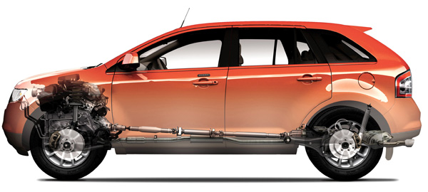
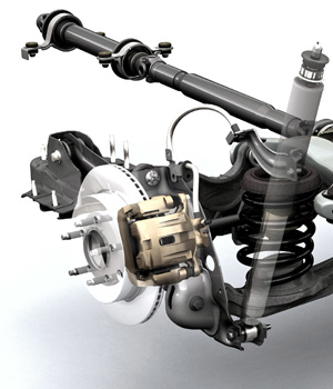
 The Ford Edge is an SUV based on a the CD3 platform. The brakes on these vehicles are straightforward and do not break any new ground. The brake systems on all variants have disc brakes at all corners.
There are no major changes to the brakes system from 2007 to 2009. For the 2008 model year, ABS became a standard feature, as did a direct tire pressure monitoring system.
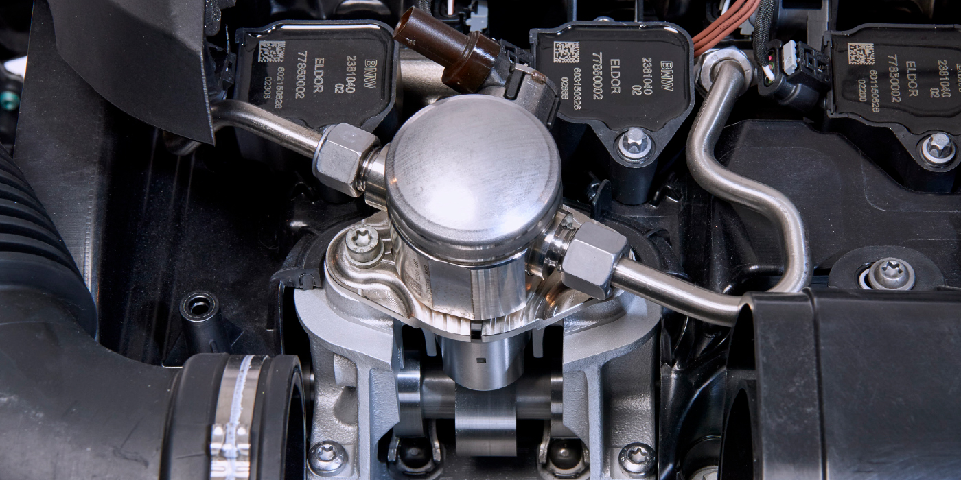
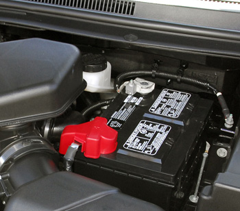
The worst brake component to service is the master cylinder. Getting to the unit requires removal of the trunking for the air intake, battery tray and other components.
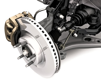
Rotors
Unfortunately, the rotors on the Edge do not have too much material. It might be difficult to get at least one turn out of the rotors before they are under spec. Overall runout and thickness variation should be less than 0.001.”
 Front Rotors:
• New thickness: 28 mm (1.10”)
• Min. thickness: 26 mm (1.02”)
• Min. thickness to machine: 27.1 mm (1.01”)
Rear Rotors:
• New thickness: 18 mm (0.78”)
• Min thickness: 16 mm (0.63”)
• Min thickness to machine: 9.1 mm (0.35”)
Front Brake Pads:
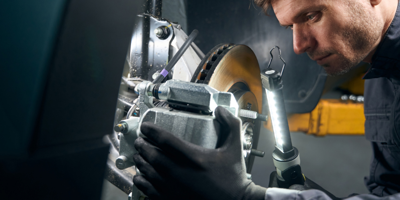
1. Retract the piston. Do not pry in the caliper sight hole to retract the pistons as this can damage the pistons and boots. Remove the two brake caliper guide pin bolts and position the caliper aside. Support the caliper using mechanic’s wire.
2. Remove the brake pads, brake pad shims and stainless steel shims. On most models, Ford used four abutment clips. Some aftermarket shims have two.
3. Inspect the brake pads and shims for wear or contamination. There should be at least 3 mm of material and the pads should not differ from side-to-side by more than 2 mm. The pads should not taper more than 2 mm.
4. Remove the brake pad slides.
Installation
1. Protect the caliper piston and boots when pushing the caliper piston into the bores. Make sure that the caliper guide pin boots are fully seated to the caliper bracket. Using a suitable tool and a worn brake pad, compress the disc brake caliper pistons into the caliper.
2. Install new brake pad slides/abutment clips.
3. Apply a thin coating of the supplied grease to the shims and the shim contact area of the brake pads.
4. Install the shims to the pads.
5. The guide pin bolts are different sizes. The longer/bigger bolt is the upper guide pin bolt. Position the brake caliper and install the guide pin bolts. Tighten to 88 Nm (65 ft. lbs).
Rotor Installation
1. Clean and dry the brake disc-to-wheel hub mounting surface and apply a thin coat of anti-seize to the mating surfaces hub’s face. Do not put on the studs.
2. Install the rotor.
3. Position the brake caliper and anchor plate assembly and install the brake caliper anchor plate bolts. Tighten to 133 Nm (98 ft/lbs).
 Rear Brake Pads:
1. Remove the two brake caliper guide pin bolts and position the caliper aside.
2. Install new brake pads if they are worn past the specified thickness above the metal backing plates. Install new brake pads in complete axle sets. Remove the two brake pads, shims and slide clips. Inspect the brake pads and shims for wear, damage or contamination. Discard the slide/abutment clips.
3. Push back the piston with the appropriate tool. Protect the caliper piston and boots when pushing the caliper piston into the bores.
4. Remove the caliper bracket if you are servicing or
machining the rotor. Clean the surfaces the make contact with the slide/abutment clips. The torque specification is 55 Nm (41 ft/lbs).
5. Install the two brake pads, shims and new slide clips to the brake caliper anchor plate. Position the brake caliper on the anchor plate and install the two guide pin bolts. Tighten to 26 Nm (19 ft. lbs).
Parking Brake
Cable tension is adjusted in two locations. The first location is at the parking brake control, the second location is at the parking brake cable equalizer. The tension must be adjusted equally at both locations.
1. With the vehicle in NEUTRAL, position it on a hoist.
2. The dimension will vary depending on the amount of cable stretch. New cables require cycling the parking brake control 5-10 times to remove the cable slack. Adjust the parking brake control adjustment so the stud protrudes 8mm ±1mm from the top of the nut.
3. Adjust the parking brake cable equalizer adjustment nut so the stud protrudes 24mm ±1mm from the top of the nut.
4. Fully apply the parking brake pedal three times to verify correct operation of the parking brake system.
5. With the parking brake cable in the fully released position, brake drag should not be present.
 Brake System Bleeding
Bleeding the Hydraulic Control Unit (HCU) is required only when removing or installing the HCU, master cylinder or opening the lines to the HCU. A scan tool with the ability to interface with the HCU is required for bleeding.
Note: Carrying out the system bleed function drives trapped air from the HCU. Subsequent bleeding removes the air from the brake hydraulic system through the bleeder screws.
Note: Adequate voltage to the HCU module is required during the anti-lock portion of the system bleed.
1. Connect the diagnostic tool.
2. Access the system bleed function.
3. Manually bleed the brake hydraulic system.
4. Repeat the procedure carrying out a total of two diagnostic tool cycles and two manual bleed cycles.
Anti-Lock System Bleed
If the vehicle is equipped with ABS, connect the vehicle communication module (VCM) and scan tool into the vehicle data link connector (DLC) under the dash and carry out the chassis brake bleeding procedure.
Manual
1. Clean all dirt from the master cylinder filler cap, then remove the cap and fill the brake master cylinder reservoir with clean, specified brake fluid. The Edge has a unique reservoir that is long and thin due to the rake of the windshield. Install the master cylinder filler cap.
2. If the vehicle is equipped with ABS, connect the vehicle communication module (VCM) and scan tool into the vehicle data link connector (DLC) under the dash and carry out the chassis brake bleeding procedure.
3. Place a box-end wrench on the right rear disc brake caliper bleeder screw. Attach a rubber hose to the right rear disc brake caliper bleeder screw and submerge the free end of the hose in a container partially filled with clean, specified brake fluid.
4. Have an assistant pump the brake pedal and then hold firm pressure on the brake pedal.
5. Loosen the right rear disc brake caliper bleeder screw until a stream of brake fluid comes out. Have an assistant maintain pressure on the brake pedal while tightening the right rear disc brake caliper bleeder screw. Repeat until clear, bubble-free fluid comes out.
6. Tighten the right rear disc brake caliper bleeder screw. Tighten to 8 Nm (71 inch lbs).
7. Repeat Steps 3 through 6 for the left rear disc brake caliper.
8. Move to the right front and then left front.
• Gravity bleeding is possible using the same sequence.