To the untrained eye, installing cylinder sleeves seems like a pretty simple procedure – these metal sleeves slip into the bore of an engine block to allow for more power, more displacement, extra strength, or repairing damage. While the latter may be true of a sleeve’s function, the former couldn’t be farther from the truth.
For those in the know, sleeving an engine isn’t a “simple” process. It takes years of experience and know-how in order to sleeve an engine properly. As aluminum continues to be a preferred material for newer engine blocks, and as existing cast iron blocks continue to be driven for more and more miles and under tougher and tougher operating conditions, sleeves continue to be the saving grace.
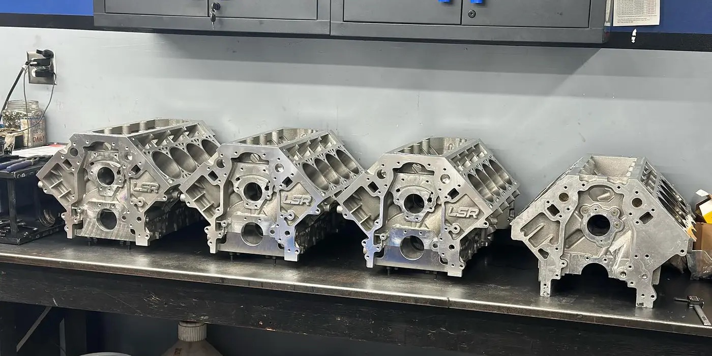
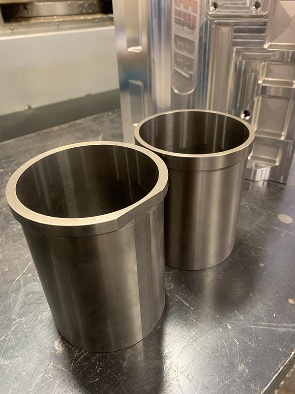
For that reason, we got some insight into sleeving from Kasey Slemmon, vice president of Esslinger Engineering, an engine machine shop focused on Ford performance in Chino, CA. Kasey has 22 years of engine building experience, and many of those years have been spent sleeving engines such as Ford Duratecs, EcoBoosts and Coyotes. Esslinger typically dry sleeves its engines using ductile iron, flanged sleeves.
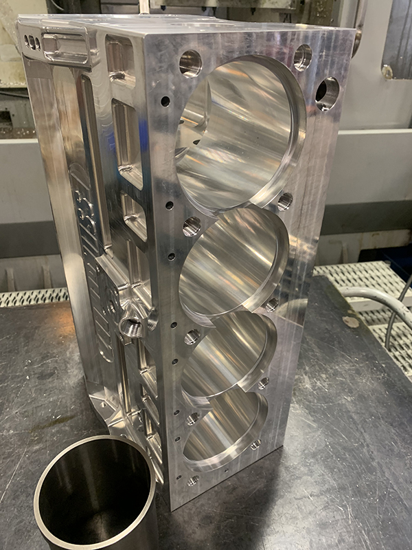
“Two engines we sleeve a lot are the Duratec and our billet Coyote engine,” Slemmon says. “Ideally, when you’re sleeving a block, you want to have the ductile iron as thick as possible, but you run into issues depending on the bore spacing of certain engines.”
In this regard, every engine is different. If you have 4.500˝ bore spacing like on a Chevy, which is very common, you’ve got quite a bit of room between sleeves that you can bore it out bigger. In modern engines, they keep becoming smaller and more compact, so you end up with less room between cylinders to overbore it.
“You always have to compromise something when you’re sleeving an engine today, unless you’re doing a really old engine that has large bore spacing,” Slemmon says. “If you compare a Coyote to the original small block Ford, the old-school 302 would look really long in comparison. You nearly have a half inch more to work with between sleeves on an older, original 302 than you do with the new, modern 302.
“When you have a half inch between the cylinders, you have more room to put a thicker sleeve in. You have more room for a bigger flange and everything follows that, such as the water jackets being spread out further, etc. However, the way the world has gone, they keep making engines smaller and more compact. You have more obstacles to overcome. You can only go so thick before you run into water or you have to end up putting slats on the sleeves because they run into each other.”
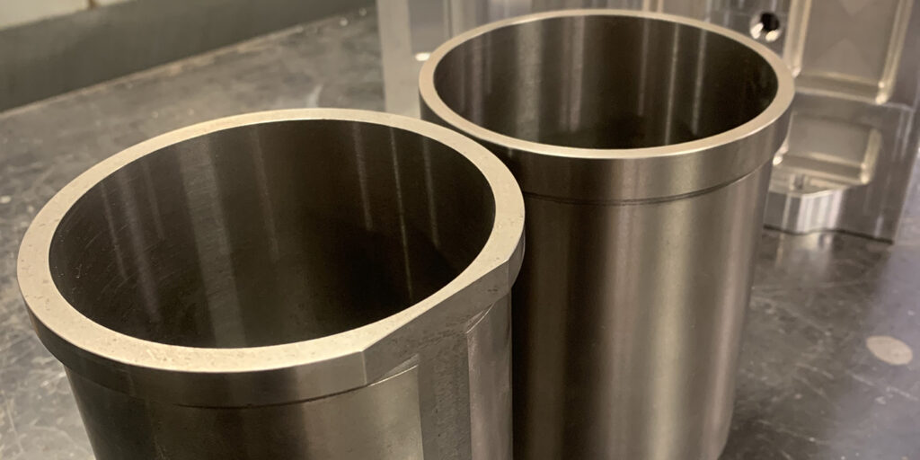
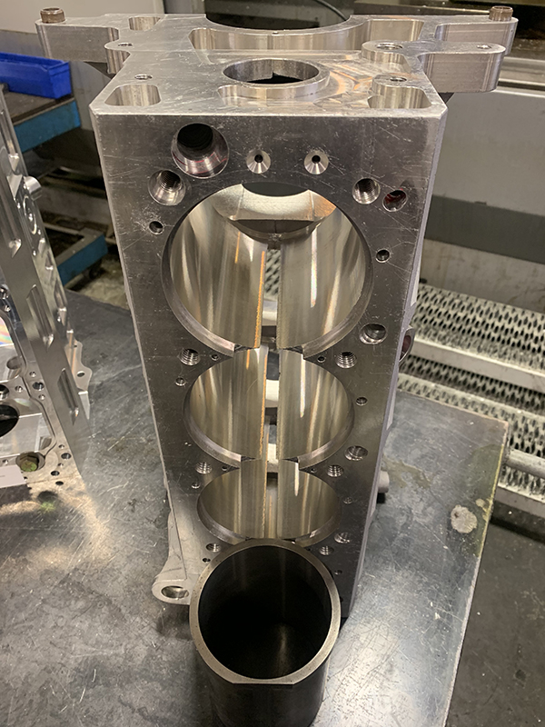
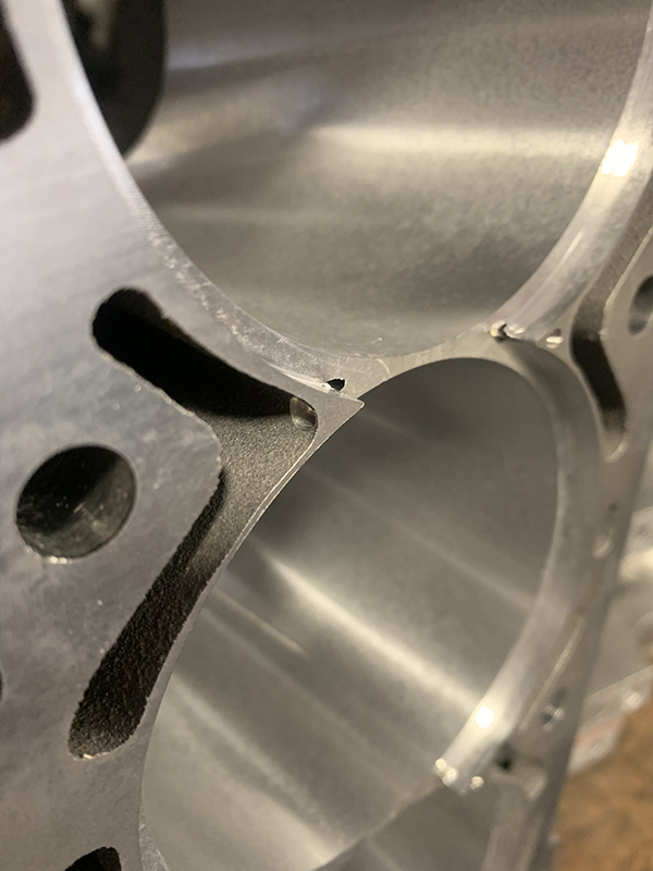
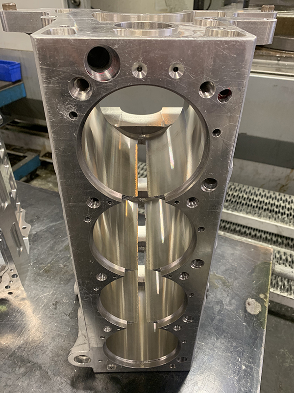
Kasey says this leads to two trains of thought when it comes to the space between sleeves. Some engine builders will leave a little bit of block material between sleeves, while others may create a small window in the bore.
“Some builders leave material between sleeves – sometimes even as thin as .050˝ – so there’s something behind the sleeve and it’s not a void,” Slemmon says. “I prefer to have a window between the aluminum, which allows you to run a thicker sleeve with more ductile iron. Then, the sleeves have a flat against a flat and you typically run about a .005˝ clearance between the sleeves that way. You rely on the sleeve holding up instead of having the aluminum behind it.”
According to Slemmon, this method helps with the ballooning effect of the bores during thermal expansion.
“You have to think about the cylinder ballooning,” he says. “Every time it combusts, that thermal expansion wants to get out of the sleeve, so that cylinder balloons. I’ve had better luck with running flats on the sleeves and leaving a window between the cylinders. That’s one of the first things you’ve got to decide in terms of set up. It’s a preference thing.”
Another preference decision is when using flanged sleeves – do you prefer the flange on the bottom or the flange on the top of the sleeve?
“People do it both ways, but I prefer to flange them at the top,” Slemmon says. “You want to get that as large as you can and a decent thickness. A good rule of thumb is you want a minimum of a .100˝ thick on the sleeve and you want a minimum of a .100˝ tall for the flange. Then, you want a 30% increase in diameter from the OD of the sleeve for the flange diameter.
“The reason why I like the flange on top is because I want the gasket embossment to fully sit on the flange. Also, in certain cases, you might want to leave the sleeve up a couple thousands above the deck. When you’re doing a really high-compression engine, it just gives it a little more crunch on the gasket embossment.”
An advantage of using a flanged sleeve is it can provide stability to the deck surface for a better head gasket seal. And, speaking of the gasket embossment, depending on how much larger you’re boring out the cylinder, you’ll want to ensure you move that gasket embossment away from the edge of the bore.
“You want to get that embossment away from the edge of the bore and you want it over the top of the flange,” he says. “You want to be over where the flange sits on the deck of the block, not into the bore or even passed where it meets the wall of the sleeve.
“A lot of guys will do wet sleeves and will put o-rings on the sleeve. They’ll have registers down on the bottom and that’s why they’ll put the flange on the bottom. They use an o-ring and a flange to keep water out of the cylinders. In my experience, (22 years) I’ve never had any luck with a wet sleeve holding up. Sooner or later, they always end up leaking water, so we don’t do wet sleeves.”
Certain engines that you run across don’t have enough material, so you have to wet sleeve them. Hondas are big with wet sleeving, but many of those engines are used for drag racing and they only run for 10 seconds at a time. To defend against potential water leaks, Esslinger Engineering always pressure tests its sleeve jobs.
“Everything we sleeve, we pressure test at double the pressure that the engine is actually running with the water system,” he says. “In newer engines, their water pressure is getting higher and higher. I don’t think that everyone who claims wet sleeves work is pressure testing it. A lot of times, they don’t even know there’s an issue unless they’re dynoing and looking for it.
“We actually test the steam content in the oil itself. What happens when you start getting water in the oil is you can get steam inside the crankcase and the crankcase can actually start pressurizing. When you have a piston coming down with a lot of wind behind it into a pressurized crankcase, that’s not good. It makes the rings flutter and things can rust. There’s nothing positive about having water leaking into your crankcase.”
The dry sleeving process can differ from engine to engine and there are lots of obstacles you have to really watch out for. If you don’t get it right, even just a little bit of water in the crankcase does a lot of damage when it turns to steam. It creates a lot of issues, and no engine builder wants that.
When it comes to installation of sleeves, it’s always a good idea to deburr the raw aluminum, because sharp edges can cause numerous issues. You also want to be able to get the sleeve 100% all the way down in the bore.
“A burr could hold it up a few thousandths, and when you go to torque the head down, the torque of the head will actually push the sleeve below the deck, and then you’re going to leak combustion because you lost clamping pressure around the embossment,” he says. “This can also lead to water leaks.”
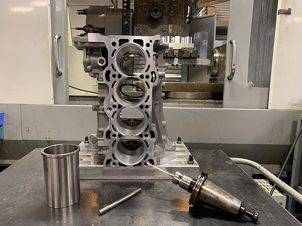
To easily install sleeves and keep them perfectly in place, Esslinger heats up the block.
“One thing we do is we heat the block up before we drop the sleeves in, and we have special tooling with clamps that hold the sleeve all the way down and we let it cool overnight,” he says. “This allows the block time to cool down and the sleeve won’t be able to creep back up.
Esslinger will even clamp the sleeves again if a sleeved block has been sitting out for a while.
“Right before we surface it, if it’s been sitting out a few weeks, we always make sure we clamp the sleeve again,” he says. “What happens is when the aluminum gets hot and cold, the sleeve starts to jimmy itself out. In an extreme situation, like if you had an aluminum block with iron sleeves in it and you left it in your shop for a year through the seasons, the hot and cold temperature changes could cause the sleeves to stick up .010˝.
“When you go to surface it and torque the head down, it’ll push the sleeve below the deck. It’s a very common thing that happens a lot. For that reason, we don’t surface a block within five minutes of taking off the tooling.”
Something else folks will want to keep in mind when sleeving a block is the temperature you heat the block to before installing sleeves.
“When you’re heating up a cast aluminum block for sleeves, don’t forget that the T6 hardness of the block is done between 400-500 degrees F,” he says. “When you heat the block up to drop sleeves in, you need to make sure you keep it below that point. I do it at 350 degrees F, just to be safe. If you go hotter than that, as you go to 400 or to where they’re actually heat treating to bring it up to T6, it will anneal the aluminum and soften it up. You don’t want to draw that hardness out of it because then it’s more prone to cracking and flexing.”
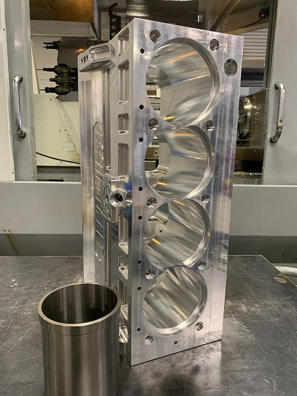
Once your sleeves are in, ensuring your sleeves are perfectly on center is also critical. You can Sonic test the thickness of the sleeves before you dial in the bore.
“If you’re not perfectly on center and you bore it more on one side, then the water jacket becomes real thin and you can break into that,” Slemmon says. “You also have to protect against a sleeve flexing because you’ve compromised its thickness or the rings don’t seal because you’re not hitting the right finish and stuff like that. It’s always best to have everything dialed in.”
Article courtesy of Engine Builder