You might not be able to see it, but an accessory drive belt is always both speeding up and slowing down. When a piston accelerates downward after the ignition of the fuel and air, the crankshaft speeds up and then slows down as it reaches the bottom of the stroke. These changes in speed are minimal, but big enough to cause problems.
If the pulses are not minimized, they can hammer the belt and the attached rotating components. On a four-cylinder engine, the degrees of rotation between power pulses are greater than on a V8 – so the amount of change in speed on the four-cylinder pulley is greater than on a V6 or V8. This has a direct effect on how the belt system is designed.
The belt drive system is working hardest when the engine is at idle. When the engine is below 1,000 RPM, the alternator, A/C compressor and power steering pump are putting the greatest strain on the belt.
Some of the forces can be taken up by the belt slipping on the pulleys, but slipping causes friction and wear on the belt, as well as flutter. Over time, the slipping can get worse as removal of material from the ribs causes the belt to bottom out.
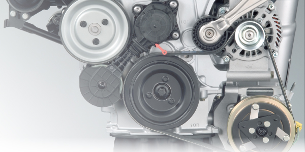
There are three components that help to keep the belt on the pulleys without slipping. The tensioner, harmonic balancer and decoupler pulley work together to keep the accessory belt system quiet and the belt lasting until the replacement interval.
Tensioner
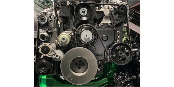
The tensioner applies force on the belt. Some tensioners have devices that dampen the movement of the spring and arm, helping to keep constant force on the belt even under a wide variety of conditions.
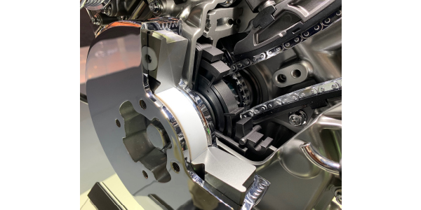
Harmonic Balancer
The harmonic dampener puts a layer of soft material between the crankshaft and outer ring of the pulley. The material helps to dissipate the power pulses and resonant frequencies. While the dampener may only flex one or two degrees of movement, this takes a lot of strain off attached components.
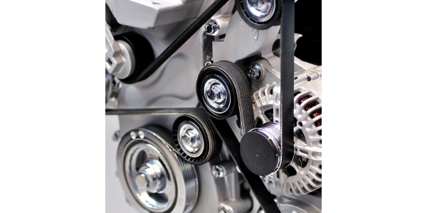
Decoupler Pulley
Some alternators have a decoupler pulley. This device serves two purposes. First, it helps to decouple the pulley from the alternator with a one-way clutch. The decoupler reduces parasitic losses by not having to fight against the momentum of the armature in the alternator while the engine is decelerating and accelerating. Some decoupler pulleys have a spring and friction dampener to reduce vibration. When an alternator decoupler pulley is compromised, it can no longer absorb the same level of abuse, which has a trickle-down effect throughout the system.
Alternator decouplers and pulleys should be inspected every 10,000 miles for wear. Early design versions have a service life of 40,000 to 60,000 miles, with more recent versions lasting more than 100,000 miles.
When inspecting a decoupler or pulley, there are two signs that replacement is needed. First, after shutting down the engine, if there is an audible buzzing, the bearings in the pulley have likely failed. The second sign depends on whether the vehicle has a one-way clutch (OWC), overrunning alternator pulley (OAP) or decoupler (OAD).
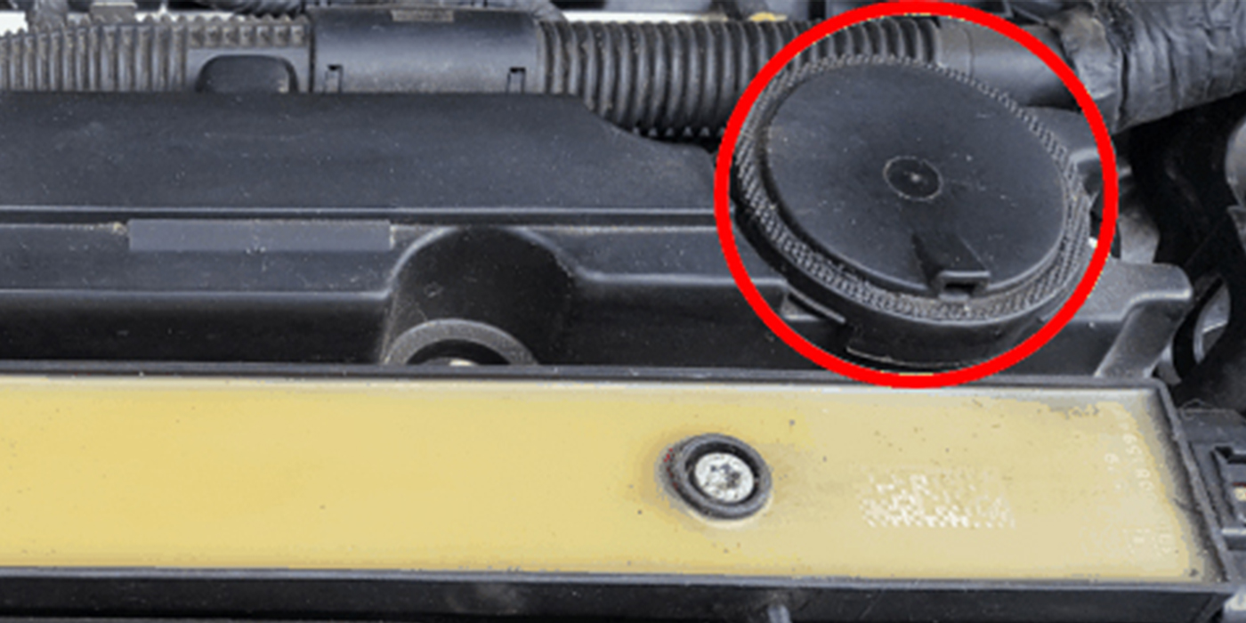
With the inspection cap/cover removed and the center locked, turn the pulley or decoupler with the appropriate tool. If it is an OAP or OWC, the pulley can only be turned in the clockwise direction. If it is an OAD, a counterclockwise turn will reveal a noticeable increase in spring force; a clockwise turn will only have slight resistance.
The tensioner, harmonic balancer and decoupler pulley work together to keep the belt in contact with grooves in the pulleys. The three components are engineered together to match the engine. If one part is compromised, all are compromised, including the belt.
Article courtesy Underhood Service.

