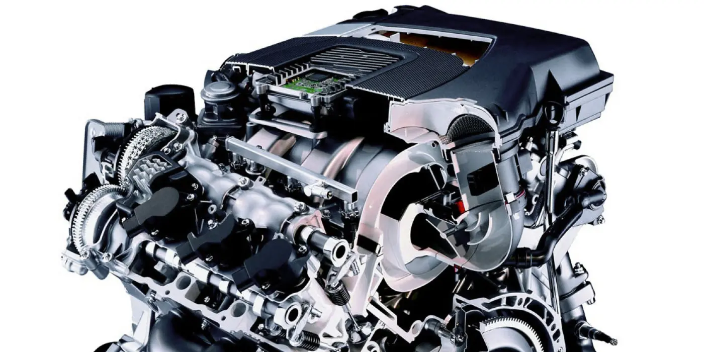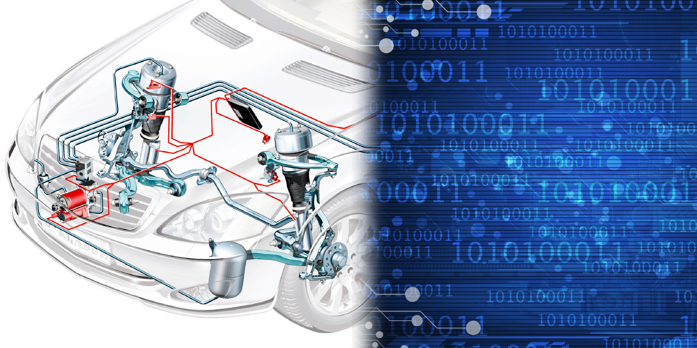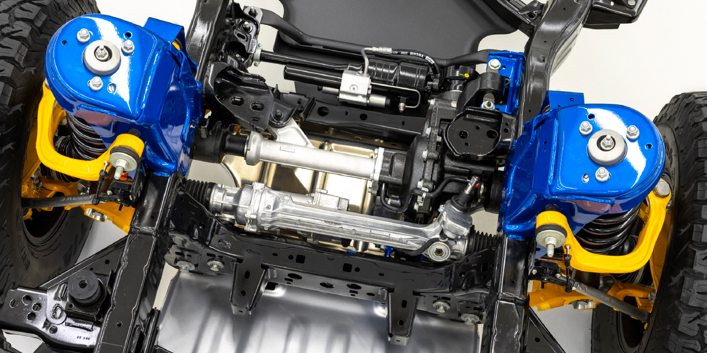
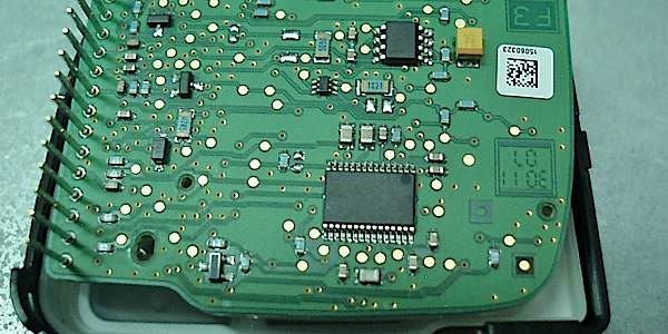
The ECM’s (engine control computer) function is to control emissions, monitor and regulate engine functions as well as optimize engine performance and fuel consumption. Systems controlled by the ECM include: fuel injection, carburetion, EGR (exhaust gas recirculation), evaporative system, air management, TCC ( torque converter clutch) and spark timing.
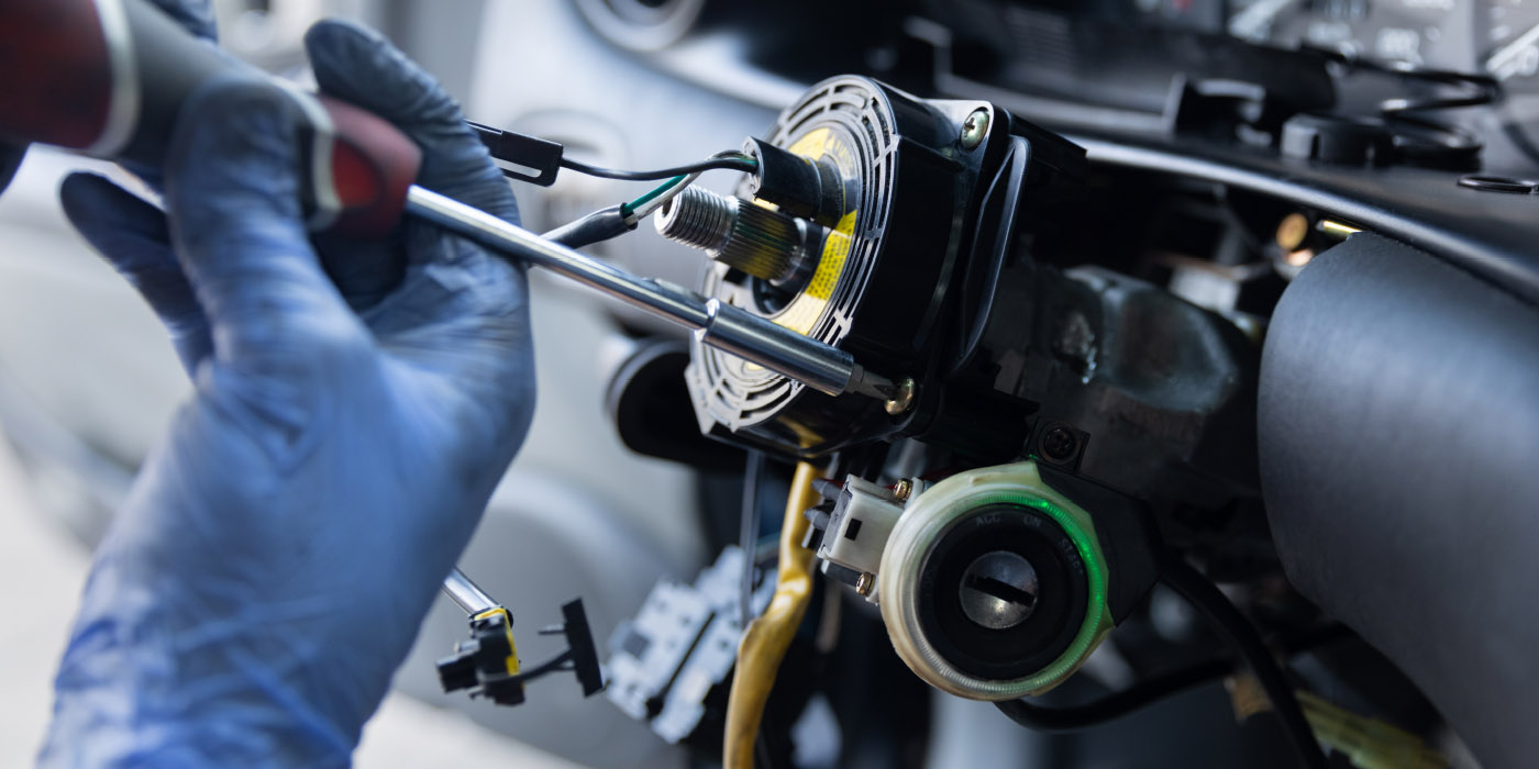
The computer is constantly updated with data (voltage signals) from the sensors (input) about engine operation. Sensors are variable resistors which modify a voltage to or from the computer. Data is analyzed by the ECM and decision commands (usually ground signals) are sent to control devices (output) based upon inputs from the sensors and ECM preprogrammed memory.
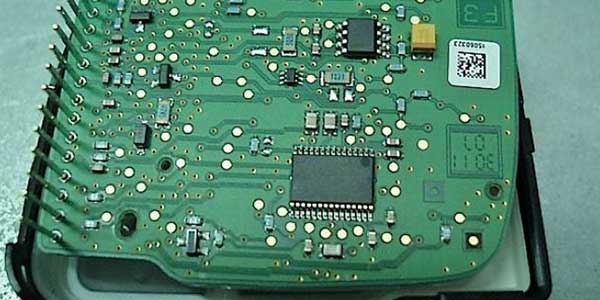
There are 3 types of memory used in ECMs. They are ROM, RAM, and PROM. Read only memory (ROM) is a preprogrammed section of memory that can only be read by the computer. If the battery power is lost, ROM memory is not lost, and is retained. Random access memory (RAM) contains information that is moved into and out of the RAM and is constantly updated. Sensor information, diagnostic codes and calculation results are stored in the RAM. The loss of battery voltage will result in lost data. Programmable read only memory (PROM) is a factory programmed set of instructions containing the calibration data for the particular vehicles’ engine, transmission, body and axle ratio. This memory may or may not be removable depending upon the vehicle manufacturer. If this memory chip (PROM) is removable, it must be transferred to the replacement unit. If the memory is non-removable, the whole ECM must be replaced.
Failure of emission system components or connections will result in the illumination of the check engine light/SES (service engine soon) light on the dash and a “trouble code” being stored in the memory. Retrieval of the code(s) will identify the problem circuit. This allows the technician to concentrate on the specific circuit affected and perform repairs accordingly. Function tests are then performed to assure the repair is good and the system is functioning properly.
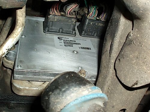
ECM’s rarely fail by themselves. Most ECM failures occur due to overloaded circuits caused by shorted solenoids and/or relays (outputs) that do not meet specified OHMS resistance. All ECM controlled components MUST be checked for proper resistance before the replacement unit is installed or premature failure will result. Bad ground circuits and improper voltages can also lead to erratic operation or damage to the ECM. Voltage supplies should be checked and verified. Grounds should be tested by performing a voltage drop test.
To perform a voltage drop test, switch the DVOM (digital volt, ohmmeter) to the low volts or millivolt setting and put the positive lead of the meter to the negative terminal of the battery and the other lead to the ground circuit at the ECM. The voltage reading should be less than .5 volts, check with the system under a load while wiggling the wires. Voltage over .5 needs to be repaired.
Defects in original equipment ECMs are identified and corrective action taken to upgrade and improve the units. CARDONE engine control computer upgrades include: upgraded components installed in critical circuits, installation of heavier injector transistors, circuit protected quad drivers, reflow of solder joints, and an upgraded power supply diode for the ignition circuit to improve durability.
Of the ECM units returned to the factory as defects, 80% test good, 15 % are customer induced failures (shorted solenoids, relays, burnt components), and 5% are alleged factory defects (check engine light bulb flickers). ECM market replacement percentages are as follows: 69% are GM, 16% are Ford, 13% are Chrysler and 2% are imports.
Courtesy of Cardone Industries.