For a number of reasons, the trend of modern engine management technology is leaning toward using coil-on-plug (COP) ignition systems. 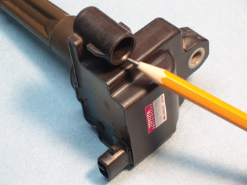
One reason is that COP ignitions are very compact and are very adaptable to individual cylinder tuning. With the exception of a few designs that incorporate a driver or “module” into the COP assembly itself, most COP systems are two-wire systems with a 12-volt power source leading to the coil and a ground wire leading from the coil to the coil driver located in the Powertrain Control Module (PCM).
By using various data inputs, including engine speed, calculated engine load, throttle opening and coolant temperature, the PCM can calculate the spark advance needed for maximum power and fuel economy, and minimum exhaust emissions under various operating conditions.
The Primary Charge
To keep the concept of producing a high-voltage spark simple and to the point, let’s say that we can create an electromagnet by wrapping an insulated wire around a large nail or similar soft iron core and “saturate” the windings by introducing a direct current into the wire.
This wire is called the primary circuit. The strength of the resulting electromagnetic field depends upon the number of wire wraps around the core and the combined voltage and amperage (wattage) of the current flowing through the wire. If the flow of electricity is suddenly interrupted, the magnetic field collapses and oscillates through the primary circuit until original voltage potential is dissipated.
The Secondary Charge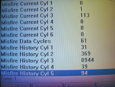
An ignition coil is created when an additional set of wires (the secondary circuit) is wrapped around the electromagnet assembly to capture the energy of the collapsing magnetic field. When the number of secondary windings is increased to capture the collapsing magnetic field, our basic 12-volt, five-ampere primary current can ultimately be multiplied into voltages ranging from 30,000 to more than 60,000 secondary volts.
This secondary voltage is more than enough to bridge the spark gap of a spark plug operating under a dynamic cylinder pressure of well over 100-150 pounds per square inch on the cranking compression stroke.
The sole limitations of any ignition coil is the amount of current that can be carried through the primary windings and the time it takes to create a strong magnetic field or to “saturate” the primary windings.
If the duty cycle or saturation time is excessive, the coil will overheat. Unlike configurations in which one coil serves multiple cylinders, the coil-on-plug design serves a single cylinder, which means that duty cycle and saturation times can be increased without overheating the coil.
Adaptive Technology
At first glance, COP ignitions seem complicated, but the opposite is true. For example, coil-on-plug ignitions eliminate the distributor cap, rotor and lengthy spark plug cables needed to connect the coil to the spark plug.
Each of these added components also represents a potential failure point in the secondary ignition system. While not as complicated, distributorless ignition systems also require conventional spark plug cables to connect the coils to the spark plugs. See Photo 1.
An additional weakness of both distributor and distributorless ignition systems is a lack of adaptability to modern computerized engine management technology. 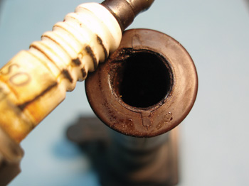
Keeping in mind that, while not all COP ignitions are equal in capability, it’s fair to say that modern engine management computers have the speed and capability to fire each spark plug multiple times during the compression and power strokes.
COP systems adapt very well to multiple spark discharge strategies because individual coils can withstand multiple saturations.
In addition, the COP design has the potential to time each cylinder according to its individual compression characteristics. In the most basic sense, compression-sensing ignition works by bridging the spark plug gap with approximately 80 volts of electricity to measure cylinder pressure.
When the cylinder pressure increases to the point that the 80 volts of electricity will no longer ionize the air molecules well enough to bridge the spark plug gap, the PCM triggers the coil to create a high-voltage spark and ignite the air/fuel mixture.
Life on the Street
Due to the lack of component accessibility on many applications, diagnosing COP ignition systems often requires a variety of diagnostic strategies. When used in an OBD II application, a defective COP ignition will usually store a P0300 misfire trouble code in the PCM’s diagnostic memory.
In Photo 2, the scan tool screen shows misfires in all cylinders because the spark plugs are worn. But, most important, the misfire history indicates that the number three cylinder has been misfiring repeatedly due to a bad spark plug, coil, fuel injector, valve train defect, leaking cylinder head gasket or low cylinder compression.
Using this screen as an example, let’s keep in mind that many OBD II PCMs will indicate an open condition in the primary circuit by displaying P0350 through P0362 diagnostic trouble codes. 
In this case, the only available DTC is P0303, which indicates a degree of misfire that’s potentially damaging to the vehicle’s catalytic converter. Although the misfire history indicates misfires in the remaining cylinders, none have reached the threshold needed for storing a general or cylinder-specific misfire code.
Criminal Patterns
The most common failure in COP ignitions is carbon tracking or “flash over” on the spark plug insulator. See Photo 3.
Although carbon tracking is usually caused by oil, dirt or moisture creating a path to ground over the spark plug insulator, a severely eroded spark plug electrode will increase firing voltages to the point that the spark will seek the point of least resistance, which is either through the spark plug boot or down the insulator to the metal shell.
If a carbon track is found on a spark plug, an identical track will be found inside the spark plug boot.
If the boot is serviced as a replacement part separate from the coil, the boots should be replaced at the same intervals as the spark plugs. If the boot is available only with the coil assembly, the spark plugs should be replaced at the recommended intervals and care should be taken not to contaminate the boot or insulator with dirt or oil.
Diagnostic Report
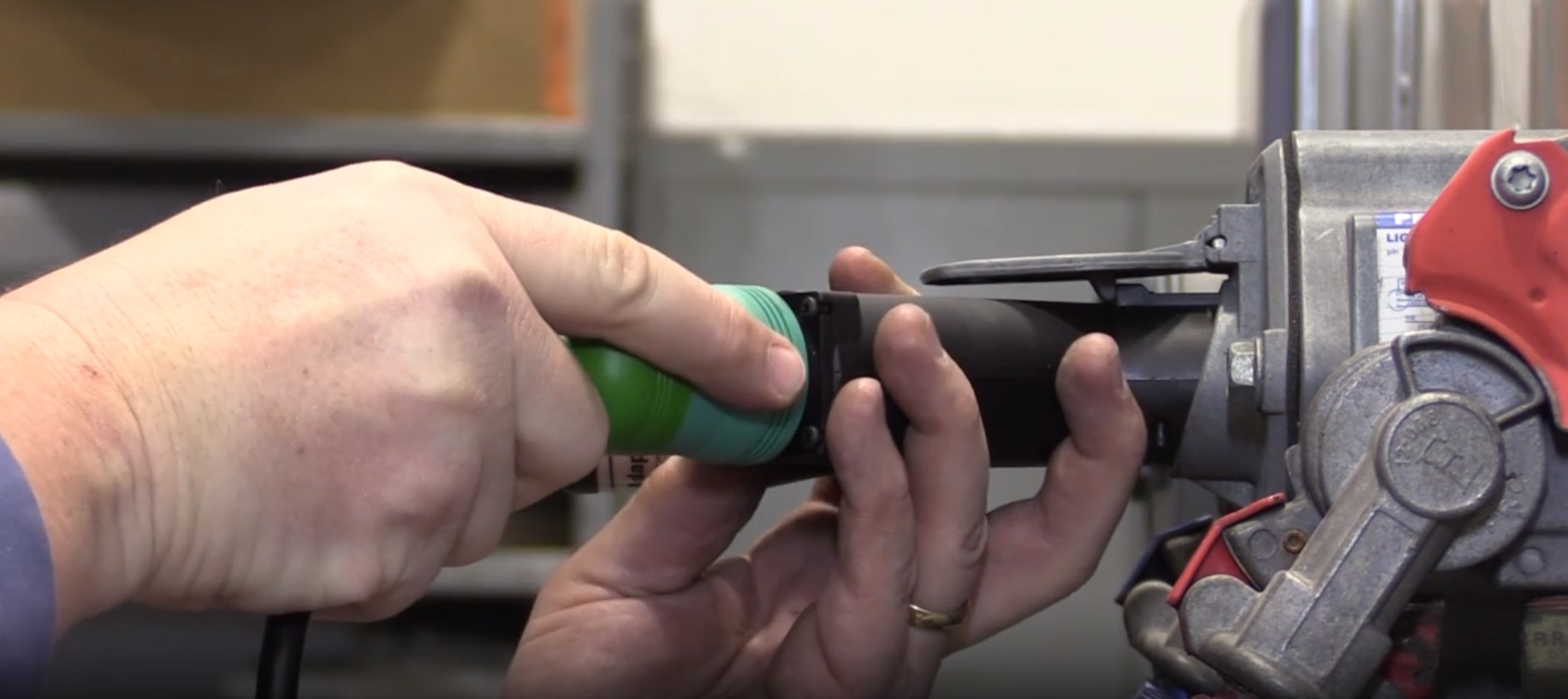
If a coil simply won’t fire a cylinder, the first step is to check the coil connector for battery voltage. If battery voltage exists and a COP assembly is suspected of causing an intermittent cylinder misfire, the quickest diagnostic procedure is to switch the coil from cylinder-to-cylinder. If the misfire follows the suspected coil, the failure will lie with the coil rather than the spark plug or PCM’s coil driver.
Many technicians like to diagnose COP ignitions with a digital storage oscilloscope (DSO) that allows the technician to test the primary waveform at the PCM or the ground connection at the COP connecter. Inductive coil adapters are also available to allow a DSO to display a secondary coil pattern. See Photo 4.
Although primary and secondary ignition waveform analysis is too complex to describe in this space, some excellent training is available through print and videotape media. In addition, live training classes are also available in areas that will support the required class sizes. One of the caveats of any scope analysis procedure is the variables encountered in different ignition system’s designs and between the displays of the scopes themselves.
Depending upon component accessibility, a skilled technician may analyze a COP ignition by using the current ramp method, a direct primary display or an inductive secondary waveform display. Whatever the diagnostic method used, coil swapping or lab scope analysis, COP ignition diagnostics are usually simple and to the point.